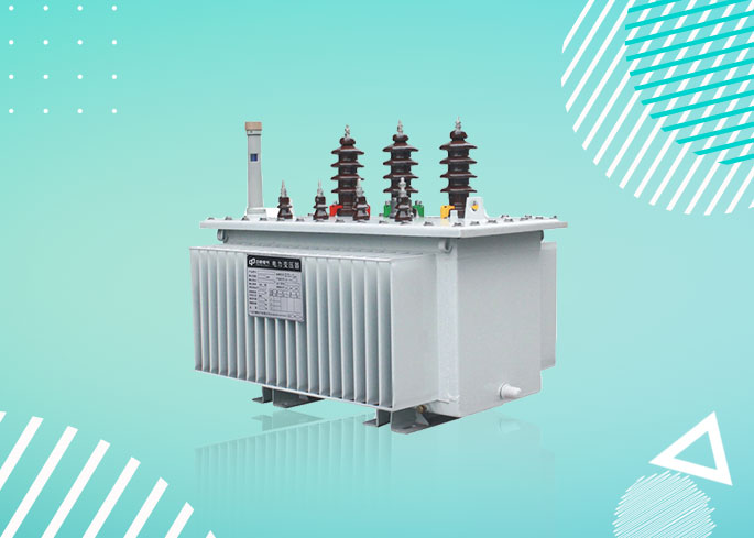
Amorphous alloy oil transformer
- Low loss: the core of transformer is coiled by amorphous alloy, and the no-load loss ratio is about 75% lower than that of S9 transformer
- Resistant to short-circuit: the transformer low voltage is made of copper foil coil to increase the capacity for undertaking short-circuit.
- Optimize the power quality: the connection group of transformer is Dynll to reduce the influence of harmonic on grid and improve the power quality.
- Maintenance-free: the tank and cover are an integrated fully-enclosed structure, long in service life and free in maintenance.
- Good insulating property: the transformer is filled with oil in a vacuum mode to completely eliminate the bubbles in coil and ensure the stable insulating property
- Installed in high-rise buildings, business centers, metros, airports, stations, industrial and mining enterprises and power plants, especially applicable to the places with high fire protection requirements such as inflammables and explosives.
Product Details
 DOWNLOAD
-
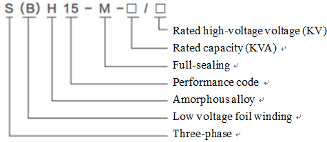
Model Description

-
Features
- Low loss: the core of transformer is coiled by amorphous alloy, and the no-load loss ratio is about 75% lower than that of S9 transformer
- Resistant to short-circuit: the transformer low voltage is made of copper foil coil to increase the capacity for undertaking short-circuit.
- Optimize the power quality: the connection group of transformer is Dynll to reduce the influence of harmonic on grid and improve the power quality.
- Maintenance-free: the tank and cover are an integrated fully-enclosed structure, long in service life and free in maintenance.
- Good insulating property: the transformer is filled with oil in a vacuum mode to completely eliminate the bubbles in coil and ensure the stable insulating property
-
Conditions of Use
- Indoors or outdoors with the elevation of less than 1,000m
- Maximum ambient temperature: +40℃, maximum daily mean temperature: +30℃
- Maximum annual average temperature: +20℃, minimum temperature: -25℃
- Transformer for special conditions can be provided according to the user's requirements
-
Technical ParametersRated capacity KVA
Voltage combinations and tapping ranges
Grade mark of connection group
Voltage combinations and tapping ranges
Short-circuit impedance (%)
No-load current (%)
Sound level LpA (dB)
High voltage (KV)
Tapping (%)
Low voltage (KV)
No-load (P0)
Load (Pk) (75℃)
30
6 6.3 10 10.5 11
±5 ±2×2.5
0.4
Dyn11
Yzn11
Yyn033
630/600
4
1.5
52
50
43
910/870
1.2
53
63
50
1090/1040
1.1
53
80
60
1310/1250
1
55
100
75
1580/1500
0.9
55
125
85
1890/1800
0.8
59
160
100
2310/2200
0.6
59
200
120
2730/2600
0.6
61
250
140
3200/3050
0.6
61
315
170
3830/3650
0.5
64
400
200
4520/4300
0.5
64
500
240
5410/5150
0.5
66
630
320
6200
4.5
0.3
66
800
Dyn11
Yyn0380
7500
0.3
68
1000
450
10300
0.3
68
1250
530
12000
0.2
72
1600
630
14500
0.2
72
2000
750
18300
5
0.2
73
2500
900
21220
0.2
73
Note: 1: When the iron core is three-phase and three-column, Yyn0 connection group can be used according to the need.
2: For the transformer with the rated capacity of 500KVA and below, the load loss above the inclined line of table is applicable to Dyn11 connection group, and the load loss below the inclined line is applicable to Yyn0 connection group.
3: Other loss values can be used if the user needs.
4: Other high voltage tapping three-phase transformers can be provided according to the user's need
-
-
-
-


